
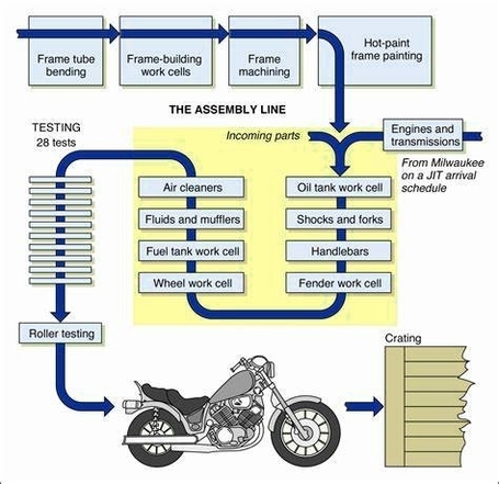
Manufacturing Process Flow 5 is a term that refers to the sequence of steps involved in producing a product or service. It can also be called a production flow chart or a manufacturing process diagram. A manufacturing process flow chart shows the stages, equipment, quality checks, and documents required for each step of the process. It helps to visualize the flow of materials, information, and resources from the start to the end of the production cycle. A manufacturing process flow chart can be used for various purposes, such as:
– Defining or analyzing new or existing processes
– Standardizing or redesigning processes
– Improving process efficiency and quality
– Identifying and eliminating waste, errors, or bottlenecks
– Communicating and documenting processes
There are different types of manufacturing process flow charts, depending on the level of detail, the layout, and the symbols used. Some common types are:
– Linear flow chart: A simple and straightforward flow chart that shows the sequential order of the process steps using arrows and rectangles.
– Swimlane flow chart: A flow chart that divides the process steps into different categories or roles using horizontal or vertical lanes. This helps to show the responsibilities and interactions of different departments, teams, or individuals.
– Value stream map: A flow chart that shows the value-added and non-value-added activities, as well as the flow of materials and information, in a process. This helps to identify and eliminate waste and optimize the value stream.
– Business process model and notation (BPMN): A standard notation for modeling and documenting business processes using graphical symbols and elements. It can represent complex and dynamic processes with multiple branches, loops, events, and gateways.
To create a manufacturing process flow chart, you need to follow these steps:
– Define the scope and purpose of the process
– Identify the inputs, outputs, and customers of the process
– List the main steps and activities of the process
– Arrange the steps and activities in a logical order
– Choose the type and layout of the flow chart
– Draw the symbols and connect them with arrows
– Label the symbols and add any relevant information or details
– Review and verify the accuracy and completeness of the flow chart
– Test and improve the flow chart as needed
You can create a manufacturing process flow chart by hand or using software tools. Some examples of software tools are [ProjectManager](^1^), [SlideTeam](^2^), [Kettering University Online](