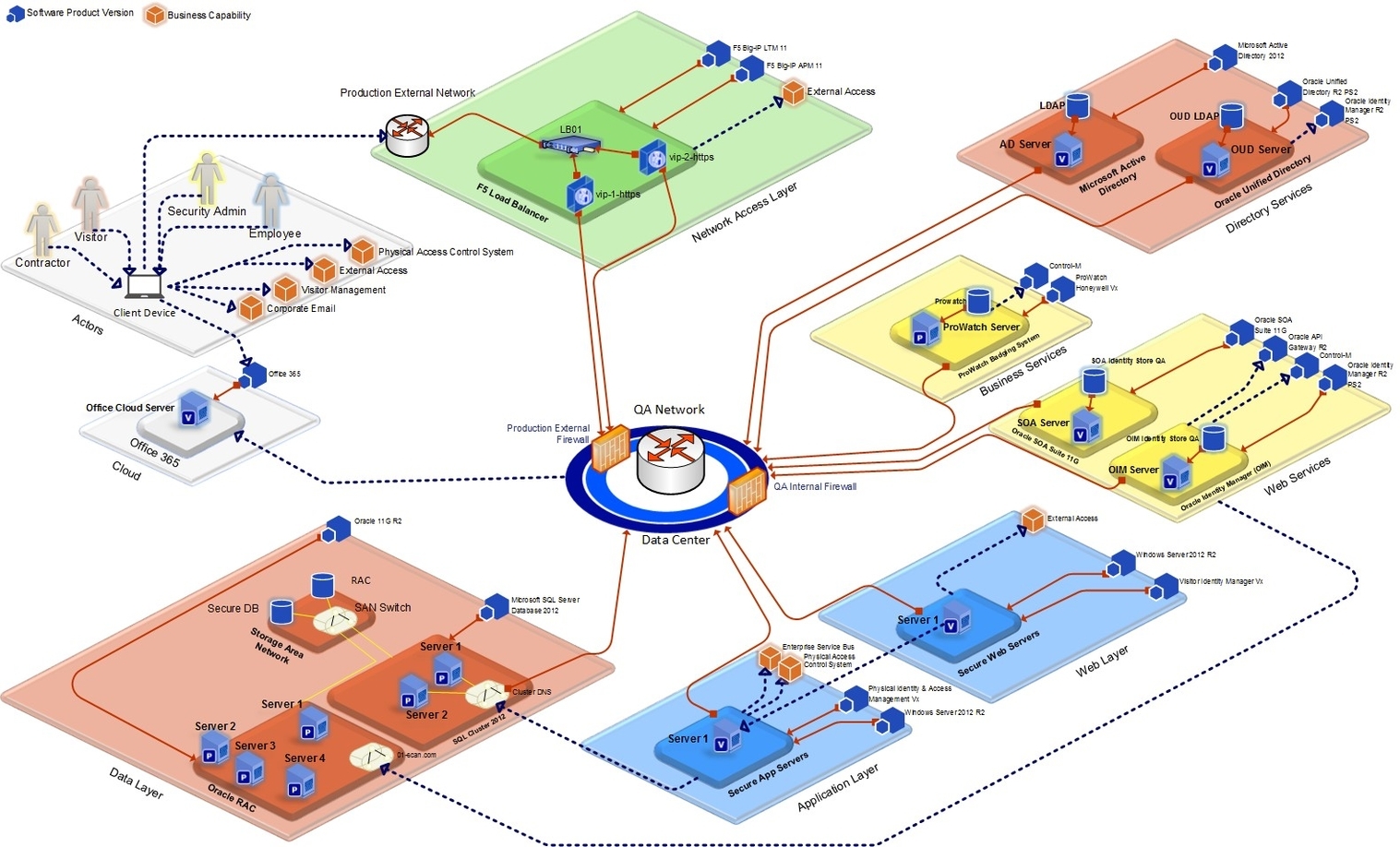
Logical Technology is a term used to describe the use of technology to solve problems and improve processes in a logical and systematic way. Microsoft Visio 2013 is a powerful diagramming tool that can be used to create a wide range of diagrams, including flowcharts, organizational charts, network diagrams, and more. In this response, I will focus on how Microsoft Visio 2013 can be used to create a conceptual, logical, and physical data model.
A data model is a visual representation of an organization’s data that depicts the connections between different data elements and is essential for database design. There are three types of data models: conceptual, logical, and physical. Conceptual models focus on the overall structure, logical models define data relationships, and physical models depict the actual implementation.
To create a conceptual data model in Microsoft Visio 2013, you can follow these steps:
1. Identify and define the entities and their relationships.
2. Create an entity-relationship diagram to illustrate the connections.
3. Add attributes to the entities to capture specific details.
4. Define the cardinality and modality to specify the nature of the relationships.
Once you have created a conceptual data model, you can use it as a blueprint for creating a logical data model. A logical data model is an essential component in data modeling, as it represents the conceptual structure of a database without getting into technical details. To create a logical data model in Microsoft Visio 2013, you can follow these steps:
1. Create a new diagram in Microsoft Visio for the logical data model.
2. Add entities and relationships to represent the organization’s data architecture, specifically the Logical Data Model.
3. Define attributes and their respective data types for each entity in the Logical Data Model.
4. Include primary and foreign keys to establish relationships between entities in the Logical Data Model.
Finally, you can convert the logical data model into a physical data model. A physical data model is a detailed representation of the data structures that will be used to build the database. To create a physical data model in Microsoft Visio 2013, you can follow these steps:
1. Open the logical data model diagram in Microsoft Visio 2013.
2. Add data types, constraints, indexes, and keys to the entities in the Logical Data Model.
3. Create tables and columns to represent the data structures.
4. Add relationships between the tables to establish the database schema.
In conclusion, Microsoft Visio 2013 is
